Detailed description of rock mass structure
Structural planes are geometric boundaries that control rock mass deformation and damage. Their production status and distribution determine the direction and accuracy of rock mass engineering geological analysis. However, the "centimeter-level" accuracy model constructed by existing non-contact measurement technology is difficult to achieve precise interpretation of the geological geometric boundaries of high and steep slopes. The accuracy of structural plane identification and simulation is not high, which seriously restricts the research on the spatial production status and distribution rules of rock mass structural planes. To this end, the team proposed a chain system of "millimeter-level" high-precision model construction → multi-source interpretation of structural surfaces → three-dimensional reconstruction of rock mass structures, so that the structural surface system of high and steep slopes can be "clearly seen, measured and measured. "Accurate", which greatly improves the accuracy of research on rock mass structural catastrophes. Relevant results have been applied to the collection of high-level structural surfaces and unstable blocks above the entrance and exit of the tunnel in the Qamdo - Lingzhi section of the Sichuan-Tibet Railway (slope height >500 m ) and the entrance and exit of the Ganluo section of the Chengdu-Kunming Railway (slope height >300 m ) is being identified.
First. Construction of “millimeter level” slope surface model for high and steep rock slopes
For the first time, rock mass engineering geological elements were integrated into non-contact measurement, and a UAV multi-angle close-in photogrammetry plan was proposed. This plan takes into account complex terrain and different structural surface production characteristics, and establishes a technical system of "initial terrain snapshots - multi-angle close-up detailed shots of geological elements - supplementary shots of key areas " , and successfully improved the accuracy of the slope surface model from " centimeter level" " Breakthrough to the "millimeter level" has effectively driven the breakthrough in the identification of rock mass geometric boundaries, allowing the distal structural planes and inverted hidden structural planes to be "clearly seen and accurately measured", promoting a fundamental improvement in the accuracy of structural catastrophe research.

Figure 1. Principle of "millimeter level" modeling technology
Second. Structural plane multi-source interpretation technology
The first parallel high-performance computing optimized identification algorithm based on point clouds achieves the goal of "fast calculation" of planar structural surfaces; at the same time, the two-pronged approach of deep learning and thermal infrared technology breaks through the "unsolvable" bottleneck of linear structural surfaces and builds a large-scale An efficient identification platform for complex structural surfaces.
1. Neighborhood growing algorithm realizes automatic and efficient interpretation of planar structural surfaces
In response to the need for efficient identification of large structural surface systems, the research team proposed a neighborhood growing algorithm, which not only simplifies the calculation process with less logical judgment, but also supports parallel computing mode, which can calculate multi-region data at the same time, greatly improving Improved point cloud computing speed. Based on this algorithm, an efficient identification platform for structural planes is built, which can achieve precise interpretation of tens of millions of point clouds and thousands of planar structural planes in an area of tens of thousands of square meters within tens of minutes.
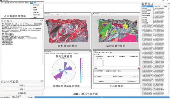
Figure 2. ARFD-RMS
2. Deep learning helps break through the problem of identifying small linear structural surfaces
In view of the gaps in the large database of rock mass linear structural surfaces, the research team used Labelme to mark linear structural surfaces in drone images from many places across the country, and established a database containing thousands of labeled pictures of complex linear structural surfaces of rock masses. A huge database provides a solid data foundation for model training. Based on this database, the YOLOv8 network model of deep learning is used for training and learning, thereby achieving efficient automatic identification and interpretation of small linear structural surfaces of rock masses in real application scenarios, and providing practical solutions for problems that are difficult to interpret linear structural surfaces. s solution.

Figure 3. Deep learning identifies small linear structural surfaces
3. Thermal infrared technology empowers the identification of large linear structural surfaces
For the first time, "physical" representation is introduced into the field of linear structural surface recognition. By carrying out long-term thermal infrared monitoring of rock slopes, the thermal infrared characteristics of linear structural surfaces were clarified, and millimeter-level crack identification was achieved in collaboration with optical images. This method overcomes the problem that existing identification methods are easily affected by optical conditions, greatly improves the abundance of optical hidden crack detection, and can be effectively applied to linear rock mass structure identification.
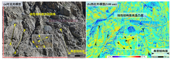
Figure 4. Physical characterization used for linear structural plane identification
Third. Three-dimensional fracture network simulation
The research team proposed a set of three-dimensional structural simulation methods suitable for large-scale complex irregular slope tables constructed with "millimeter-level" models. This method makes up for and breaks through the shortcomings of the traditional method of tedious mathematical derivation and huge amount of calculation, and greatly improves the speed and accuracy of three-dimensional simulation of structural surfaces. It has realized the expansion of application scenarios from "simple plane" to "large complex irregular slope surface", more comprehensively captured the overall structural characteristics of large-scale engineering rock masses, and provided more accurate internal information for the stability analysis of rock mass engineering structures. Boundary reference.
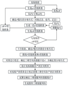
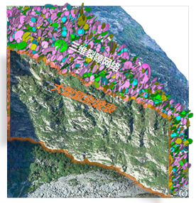
Figure 5. Large window 3D fracture network simulation technology flow chart
Figure 6. Example of three-dimensional crack network simulation results for a complex slope surface.